X-Wiife app for X-IFIED Training Simulator
User's Guide
Description
The X-IFIED training simulator is available with optional WiFi or Bluetooth modules and matching X-Wiife Android app.
While the app can run on a variety of devices, the recommended device is a tablet as the controls may be a little too small for a phone display.
The tablet should be running Android version 4.4 or more recent, with 512MB of RAM minimum and a 640x480 display. For optimum performance, the recommended configuration is Android 5.1 or later with a display size of 7" or 8", 1280x800 resolution and 1GB RAM.
These manual pages describe how to connect the tablet to the device, and how to operate the device through the app.
WiFi Connection
The recommended connection method uses the Soft-AP feature of the WiFi module. It allows the tablet to connect to an X-Wiife without the use of a WiFi router/access point. It is very convenient when the intent is to control a single unit at a time in a single geographic location.
Soft-AP method: The X-Wiife devices have been configured to appear as a WiFi access point with an SSID of X-Wiife-xxxx where xxxx is a unique hexadecimal number. This is called the Soft-AP mode. To use the Soft-AP mode, you need to open the WiFi setup page of the tablet and join the X-Wiife-xxxx access point. The IP address of the X-Wiife device in the Soft-AP mode is 10.10.100.254. Once this is done and the tablet indicates that it has joined the network, start the X-Wiife app.
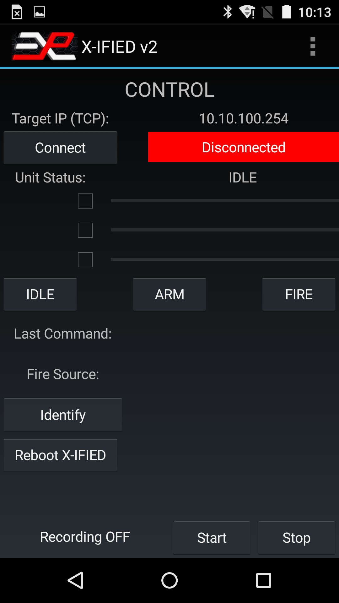
Figure 1: X-Wiife WiFi app main page, disconnected
WiFi Setup: To make sure the app is configured to use the WiFi connection method, click on "WiFi Setup" in the menu (click the three dots at the top right of the screen to open the menu).
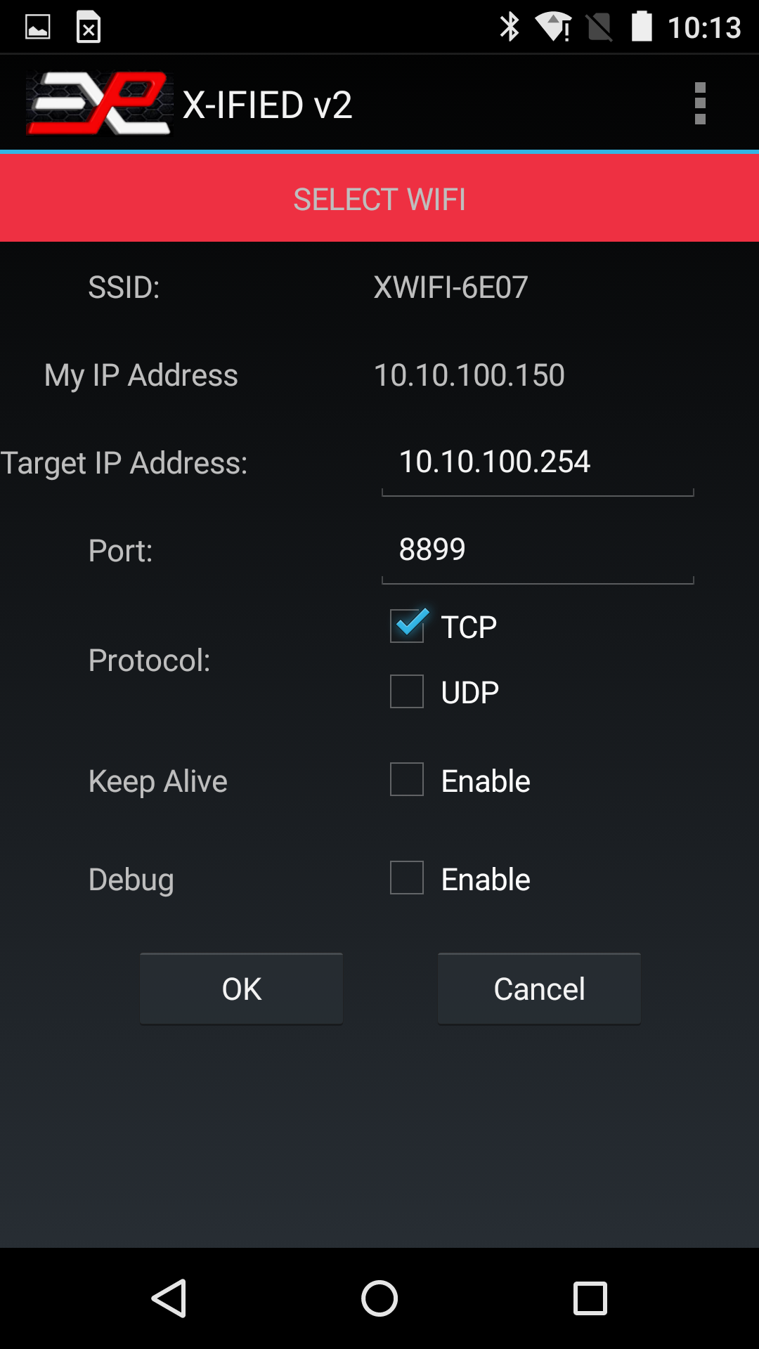
Figure 2: WiFi Setup page
Use the default settings:
- Target IP Address: 10.10.100.254
- Port: 8899
- Protocol: TCP
- Keep Alive: unchecked
- Debug: unchecked
Click OK, which will return you to the Control page.
Bluetooth Connection
Before configuring the app for Bluetooth operation, you need to pair the tablet with the Bluetooth module on the X-IFIED.
Power up the X-IFIED and enter the Bluetooth setup on the tablet. The Bluetooth module has an ID of "HC-05" and the pairing key is "1234". Once the tablet and Buetooth module are paired, enter the Bluetooth setup page on the app.
Bluetooth Setup: To access the Bluetooth setup page, click on Bluetooth Setup in the menu.
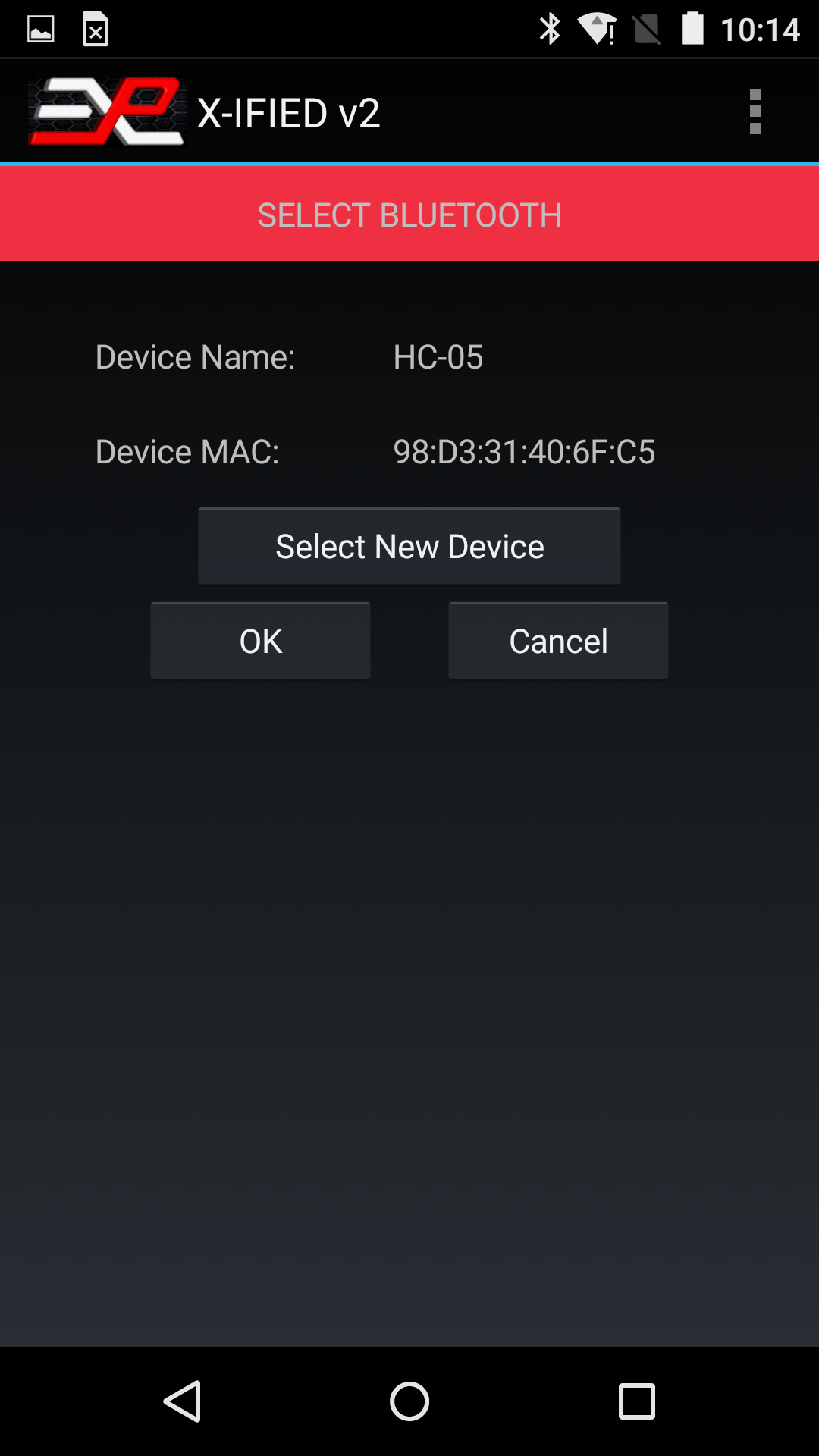
Figure 3: Bluetooth Setup page
Make sure the HC-05 device is selected and click OK. There are no custom setting for the Bluetooth option.
Operation
Once the interface has been selected (as shown at the top of the Control page), click on the “Connect” button. The app should establish a connection with the X-IFIED and display the status. The “Connect” button now indicates “Disconnect” and the red label turns green and indicates the ID string and firmware version of the X-IFIED. The picture below shows a typical status with voltages applied to two of the analog inputs.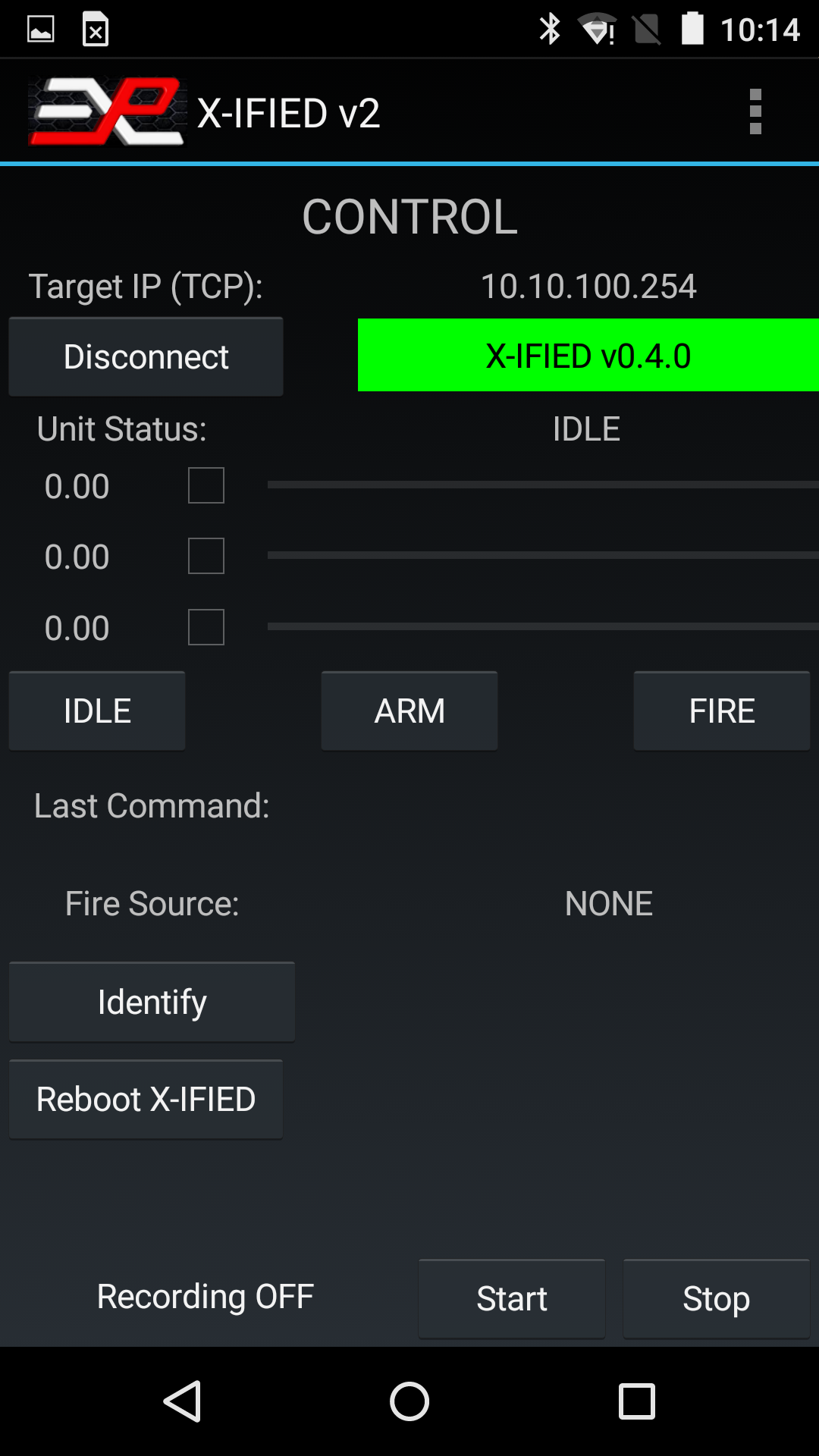
Figure 4: X-Wiife WiFi app main page, connected
The X-Wiife app offers 3 main modes of operation, accessed through the menu (three dots at the top right corner of the display.)
- Control: This is the normal use of the app. The Control mode allows to monitor the state of the device and send commands to change the state to ARMED, FIRING or IDLE.
- Settings: This page allows to change the operating parameters (delays, voltage thresholds, operation of the buzzer and LEDs)
- Debug: This page is used for troubleshooting and also displays the event log.
Control
“Unit Status” indicates the state of the X-IFIED, IDLE, ARMING DELAY, ARMED, FIRING or FIRING DELAY. It may also indicate ERROR if, for example, a fire input on the X-IFIED device was asserted while the unit was in IDLE state.The 3 numbers and matching progress bars represent the voltage on each of the analog inputs.
If the checkbox near a number is checked, this number (and the progress bar) now represents the percentage of the trip point achieved by the voltage present on the input, i.e. the progress bar is an indication of how close the input voltage is to the trigger point.
If the checkbox is not checked, the progress bar represents the fraction of the full range voltage of the input, 21.68V as of firmware v0.3.0.
The three buttons, IDLE, ARM and FIRE are self-explanatory. Note that the tablet will beep if the X-IFIED is fired, regardless of the origin of the fire command.
The “Last Command” box shows the last command sent to the X-IFIED from the tablet.
The “Fire Source” box shows which input triggered the fire state, or “NONE” if the fire state has not been triggered yet.
The “Identify” button can be used to force the X-IFIED to blink its status LED D4 fast. This can be useful if there are multiple X-IFIEDs powered at the same time and the operator is not sure of what unit he is controlling (this feature is only useful when the WiFi router connection method is used.) The Identify mode is turned off by changing the X-IFIED state (IDLE or ARM button.)
Settings
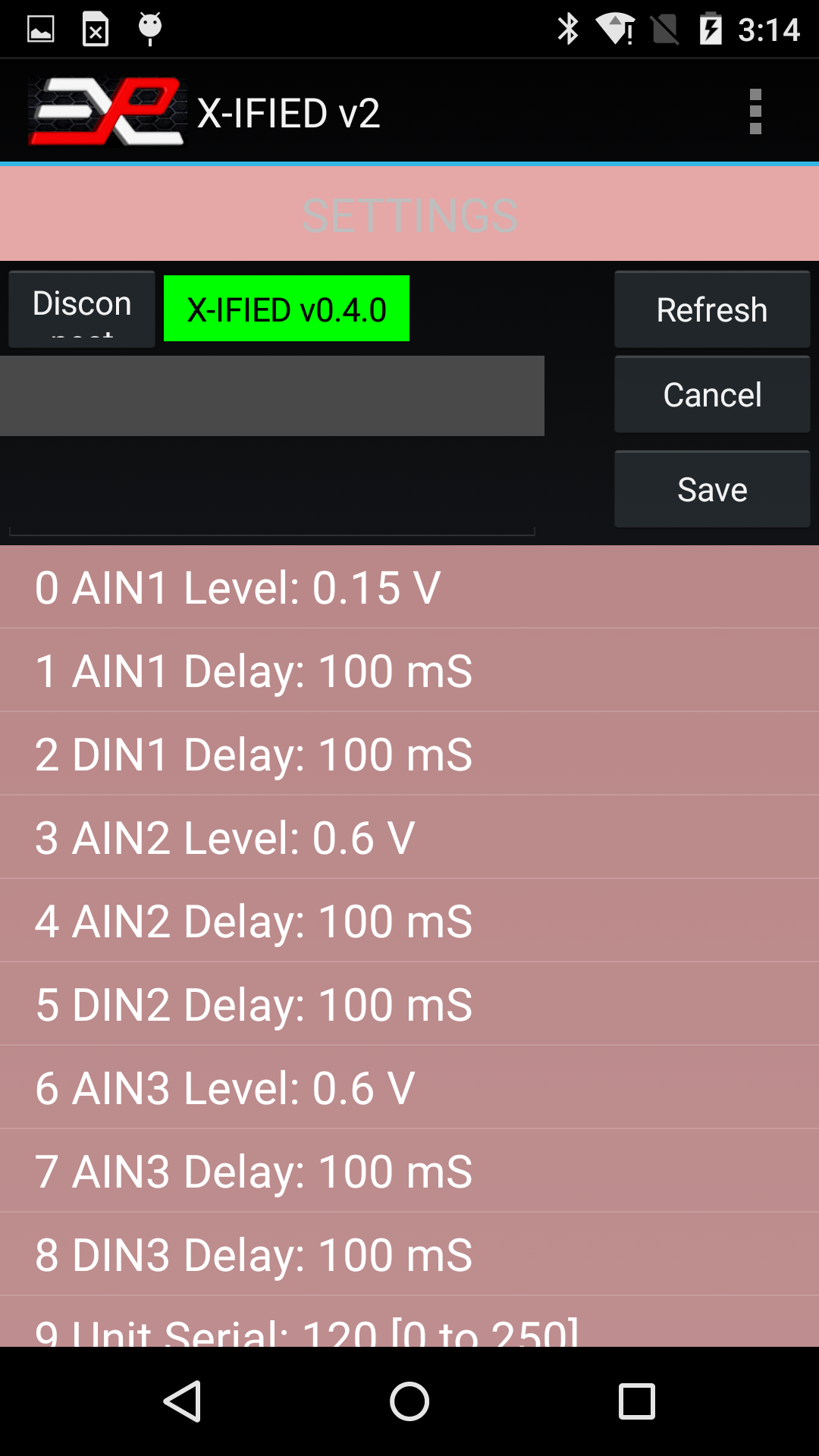
Figure 5: X-Wiife Settings page
If the X-Wiife is not connected or has disconnected, click on the “Connect” button. Otherwise, if the Unit ID label is green, click on the “Refresh” button. The app will query the available settings for the X-IFIED and display them in the central list box (white text on pink background). See figure 8. The second list box at the bottom of the screen (white text on black background) is for troubleshooting and can be ignored.
Refer to Table 9 for the description of the various settings.
| Parameter | Function | Options |
|---|---|---|
| AIN1 Level | Select trigger level for Analog Input #1 If Disabled is selected, this input cannot be used for normal functions and it can be used to simply monitor a voltage via the WiFi interface. | 0.07V, 0.15V, 0.3V, 0.6V, 1.2V, 2.5V, 5.0V, Disabled |
| AIN1 Delay | Select how long the level on AIN1 must be above the trigger point to assert the selected state | 3mS, 10mS, 30mS, 100mS, 250mS |
| DIN1 Delay | Select how long DIN1 must be activated before asserting the selected state | 3mS, 10mS, 30mS, 100mS, 250mS |
| AIN2 Level | Select trigger level for Analog Input #2 If Disabled is selected, this input cannot be used for normal functions and it can be used to simply monitor a voltage via the WiFi interface. | 0.07V, 0.15V, 0.3V, 0.6V, 1.2V, 2.5V, 5.0V, Disabled |
| AIN2 Delay | Select how long the level on AIN2 must be above the trigger point to assert the selected state | 3mS, 10mS, 30mS, 100mS, 250mS |
| DIN2 Delay | Select how long DIN2 must be activated before asserting the selected state | 3mS, 10mS, 30mS, 100mS, 250mS |
| AIN3 Level | Select trigger level for Analog Input #3 If Disabled is selected, this input cannot be used for normal functions and it can be used to simply monitor a voltage via the WiFi interface. | 0.07V, 0.15V, 0.3V, 0.6V, 1.2V, 2.5V, 5.0V, Disabled |
| AIN3 Delay | Select how long the level on AIN3 must be above the trigger point to assert the selected state | 3mS, 10mS, 30mS, 100mS, 250mS |
| DIN3 Delay | Select how long DIN3 must be activated before asserting the selected state | 3mS, 10mS, 30mS, 100mS, 250mS |
| Unit Serial | Serial Number | |
| Arming Buzzer | Enable/Disable the BUZZER and LED during the ARMED INIT state | Yes (Enabled) or No (Disabled) |
| Arming Delay | Delay between activation of Arm Input and device achieving the Armed state | 1 sec, 10 sec, 1 mn, 10 mn, 1 hr, 5 hr, (Infinite) |
| Firing Pulse | Duration of the Firing Output Signal | 10mS, 30mS, 100mS, 300mS, 1 Sec, 2 Sec |
| Re-Firing Delay | Delay after firing and before returning to Armed or Idle state | 1 Sec, 2 Sec, 5 Sec, 10 Sec, 30 Sec, 1 Min |
| Idle Delay | Inactivity period in Armed state after which the unit returns to Idle state | 1 sec, 10 sec, 1 mn, 1 hr, 5 hr, Infinite |
| Armed LED | Enable/Disable the Armed LED | Yes (Enabled) or No (Disabled) |
| Idle LED | Yes (Enabled) or No (Disabled) | |
| IN1 Function | IN1 function can be set to one of four choices | - ARM input - DISARM input - Fire then Idle (Disarmed) - Fire then Re-Arm |
| IN2 Function | IN2 function can be set to one of four choices | - ARM input - DISARM input - FIRE then IDLE (Disarmed) - FIRE then Re-ARM |
| IN3 Function | IN3 function can be set to one of four choices | - ARM input - DISARM input - FIRE then IDLE (Disarmed) - FIRE then Re-ARM |
To change a parameter, scroll the List up and down until you see the parameter you want to change, click on the parameter. This will copy the parameter’s description and current value in the boxes just above the table (see Figure 9), and a new drop down list is displayed, showing the available settings.
Select the new setting and click the “Save” button. When done, click “Refresh” to reload the settings with the new value.
Figure 6: Changing a setting
Debug
The Debug feature is reserved for troubleshooting under guidance from Explotrain personnel.
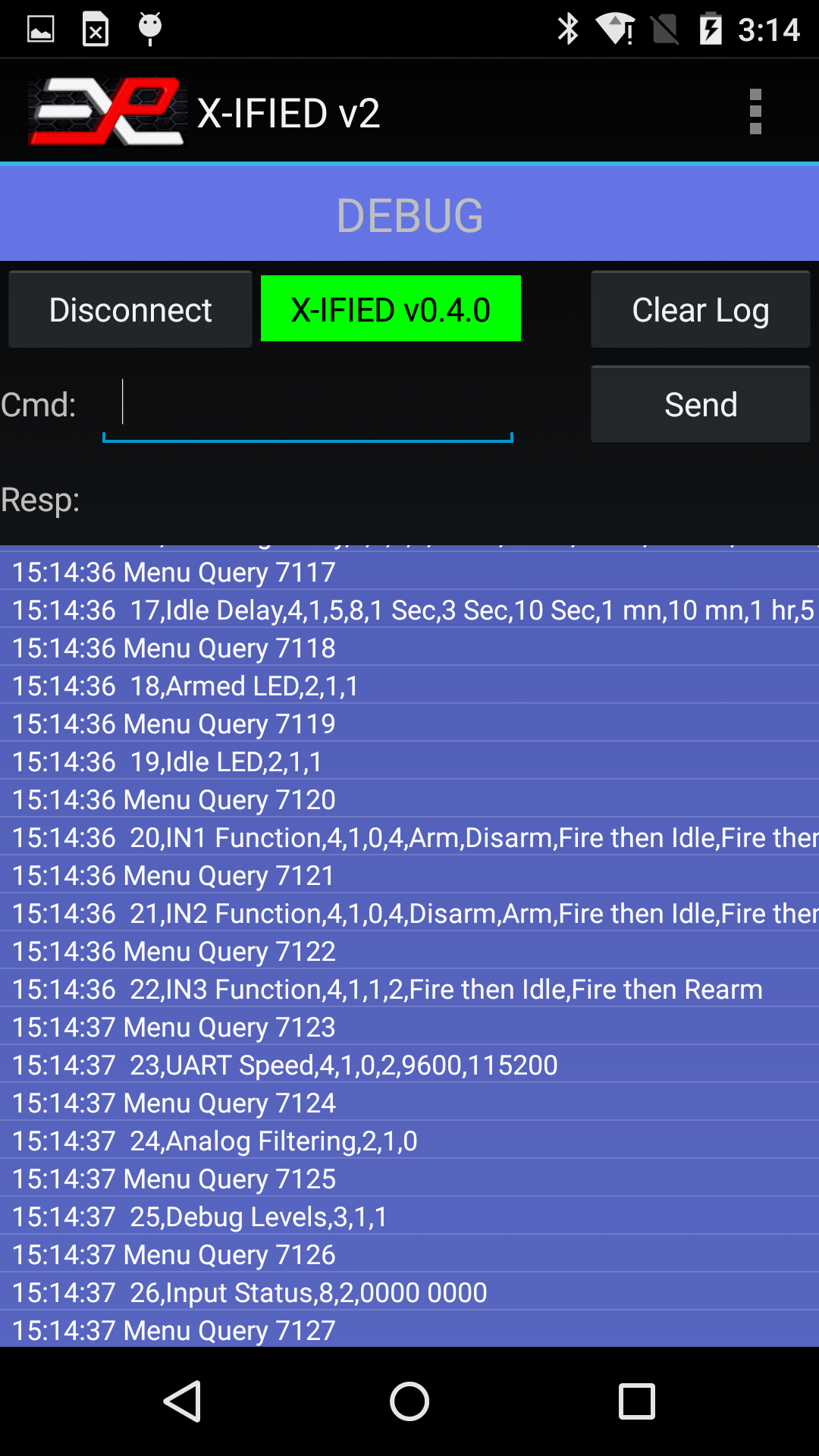
Figure 7: Debug page
The event log records all commands and actions with a time stamp and can be saved to a file on the tablet and emailed later.
The log can be useful to recall a sequence of events during training for further discussion with the trainees, or for troubleshooting.