X-ACT Manual - Shop
User's Guide (version 1.4.1)
- Description
- Installation
- WiFi Connection
- Bluetooth Connection
- Operation
- Map View
- View Currents
- Running Scripts
- Settings
- Debug
- Contact/Support
Installation
The X-ACT Bridge Controller must be installed such that it can have radio contact through the XBee module with all the simulators (X-O, X-CAL or X-RPT).
The X-ACT Bridge Controller must also be within range of the X-ACT Tablet used for control.
When coonnected via WiFi, the range between the Tablet and the Bridge Controller is about 50 to 100 feet in a building, sometimes less depending on the building construction.
WiFi Connection
The recommended connection method between the X-ACT Bridge Controller and the tablet uses the Soft-AP feature of the WiFi option in the X-ACT Bridge Controller. It allows the tablet to directly connect to the X-ACT without the use of a WiFi router/access point.
Soft-AP method: The X-ACT Bridge Controller has been configured to appear as a WiFi access point with an SSID of X-ACTXXXX where XXXX is a unique hexadecimal number. This is called the Soft-AP mode. To use the Soft-AP mode, you need to open the WiFi setup page of the tablet and join the X-ACTXXXX access point. The IP address of the X-ACT Bridge Controller in the Soft-AP mode is 10.10.100.254. Once this is done and the tablet indicates that it has joined the network, start the X-ACT app.
WiFi Setup: To make sure the app is configured to use the WiFi connection method, click on "WiFi Setup" in the menu (click the three dots at the top right of the screen to open the menu).

Figure 2: WiFi Setup page
Use the default settings:
- Target IP Address: 10.10.100.254
- Port: 8899
- Protocol: TCP
- Keep Alive: unchecked
- Debug: unchecked
Click OK, which will return you to the Control page.
Notes:
The Android operating system normally expects to be able to access the Internet when a WiFi connection is open and it will complain when it is not able to do so. It may be in the form of a message box asking you to confirm that you want to connect or it may be in the way the Android device will not automatically reconnect to the Bridge Controller if the device is able to get internet through a cellular connection. The exact behavior depends on the Android version.
In some cases (like if the Bridge Controller is powered down or moves out of range while the app is running), the app may have difficulty reconnecting to the Bridge Controller. In such cases, after reconnecting the tablet to the Bridge Controller's access point through the WiFi settings, close the app, then from the tablet's home page, click on the tabs icon (the rectangular icon at the bottom right of the display). Android will display all the apps still in working memory as below:
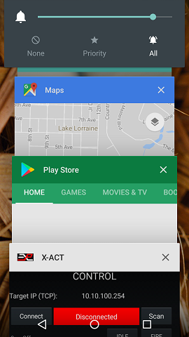
To close the app and force it to reinitialize the connection, click on the X to the right of the X-ACT banner. Then restart the X-ACT app normally.
Bluetooth Connection
When using the Bluetooth option, the range is typically 15 to 30 feet, depending on building construction.
The Bluetooth option may be preferred under certain circumstances when the X-ACT Tablet does not maintain WiFi connectivity in the absence of Internet access. This is an Android issue that varies depending on the Android device and the operating system version.
The Bluetooth module may also be prefered when it is desirable to maintain Internet access with the tablet while being operated. When using the WiFi module, the Android tablet will not be able to maintain Internet connectivity at the same time.
Before configuring the app for Bluetooth operation, you need to pair the tablet with the Bluetooth radio on the X-ACT Bridge Controller.
Power up the X-ACT Bridge Controller and enter the Bluetooth setup on the tablet. There are two types of Bluetooth radios that can be used interchangeably. One has an ID of "HC-05" and the pairing key is "1234". The other has an ID of "Sure" and the key is "0000".
Once the tablet and Buetooth radio are paired, enter the Bluetooth setup page on the app by clicking on Bluetooth Setup in the menu.

Figure 3: Bluetooth Setup page
Make sure the proper device (HC-05 or Sure) is selected and click OK. There are no custom settings for the Bluetooth option.
Connection to multiple Bluetooth devices
The Bluetooth radio can only be paired with one Android device at a time, so if you pair the Bluetooth radio with a second tablet, it will lose the pairing with the first tablet, even though the first tablet will still show the X-ACT as paired. This is a characteristic of the Bluetooth protocol as the tablet has no way to know when the Bluetooth device has reset its pairing information. If you want to re-pair with the first tablet, you will have to select it in the tablet's Bluetooth Settings -> More Settings and click "Forget" before attempting to pair again.
The Bluetooth radio only enters pairing mode for a few minutes after power up, so always recycle power on the X-ACT Bridge Controller before attempting to pair with the Bluetooth radio.
Operation
Before connecting the app, make sure the X-ACT Bridge Controller has scanned all the simulators.For that, power all the simulators first, then the X-ACT Bridge Controller. The initial scan takes about 10 seconds.
Then connect to the X-ACT Tablet to the Bridge Controller via WiFi or Bluetooth as appropriate and start the app.
If you have more than 10 devices connected, click on the menu and click on "10/16 Units" to enable the 16 Units control mode. Clicking the "10/16 Units" menu alternates between the two modes. If you have 10 simulators or less, make sure they use addresses between 0 and 9 (included) and you can use the "10 Units" mode.
In the app, click on the Connect button. In a few seconds, the screen should be populated with the simulators that are connected to the X-ACT Bridge Controller. The screen shot below shows two simulators connected.

Figure 4: X-WBridgeWiFi app main page, connected
The display indicates at the top the IP address of the X-ACT Bridge Controller and below that the "Connect" (or "Disconnect" if the app is connected) button, a label indicating the ID String and software version of the X-ACT Bridge Controller and the "Scan" button.
On the next 10 (or 16) lines, from the left: the simulator's address and its ID string, indicating the type of device it is and the firmware version, or "Off" if there is no powered simulator at this address, then the state of the simulator (only for those that are powered), then the two control buttons to the right.
Notice that the left button indicates "ARM" for the two units that are connected, and IDLE for the units that are disconnected. We will get back to this later.
Initially, the simulators will be in IDLE state. Press the ARM button, the simulator's state changes to ARMED and the FIRE button is now enabled.
To fire the simulator, click on the FIRE button. The state will change to FIRING, then FIRE DELAY and after a few seconds it will return to ARMED.
Disconnection
If the normal power-up sequence cannot be followed (powering up the simulators first, then the X-ACT Bridge Controller), it may be necessary to click on the "Scan" button to force the X-ACT Bridge Controller to restart the power up scanning sequence. Pressing the Scan button will disconnect the app from the X-ACT Bridge Controller. This is normal. Simply wait 10 seconds before reconnecting to make sure the scanning sequence is complete. Note that to use the Scan button, the app needs to be in the connected state to the X-ACT Bridge Controller.It may happen that a simulator that is at the edge of the useful range randomly disconnects from the X-ACT Bridge Controller. The indication will be that the app stops displaying the state of that simulator. If that happens, it may be possible to reconnect without rescanning simply by clicking the IDLE button for that simulator, but it is best to resolve the range issue for reliable operation.
Rename Simulators
When a large number of simulators are used, it may be preferable to display useful names instead of displaying the simulators ID strings.
To rename the simulators in the app, click on the menu then on "Show Names/IDs". This menu toggles the display of names or ID strings, then click on the menu and then on "Edit Names On/Off". A label at the bottom of the screen indicates when you are in Edit Name mode.
To change the name assigned to a simulator, click on the label currently displaying "Undef" for that simulator. Enter the name you want displayed and click on Ok.
When done, click on the menu and then on "Edit Names On/Off" to turn off the edit mode.
Simulator Fault
Simulators with firmware 2.0.0 and up can display a fault status when some parameters are exceeded or if the battery voltage is too low. When in Fault mode, the simulator's status will be displayed in red as in the picture below.
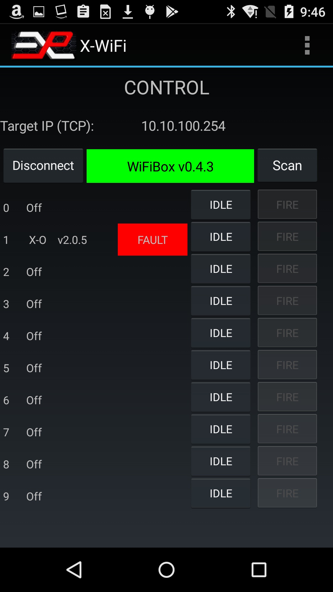
Figure 4a: Fault Status
In the example above, the simulator at address 1 shows a Fault condition.
To display the type of fault, simply click on the red "Fault" status label. A popup list will indicate the type of fault and give you options to clear or ignore the fault.
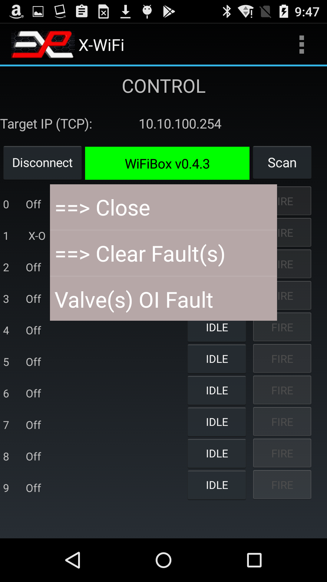
Figure 4b: Fault Report
In this example, the popup shows that the simulator faulted because of valve Over Current.
By clicking on the "Clear Fault(s)" message, you can return the simulator to normal operation. However, unless the cause of the fault has been eliminated, it is very likely to come back. Look in the Settings section for more information on fault troubleshooting. If you hit Close, the popup will close without further action.
Map View
To select Map View, click on the menu and select Map View.The Map View offers a graphical representation of the simulators superimposed on a map of your choosing. It could be a map downloaded from Google Maps or any other online provider, or a picture of a hand drawn map.
The app is installed with a sample map. To use it, click on the menu, select Pick New Map and select "map_sample.png".
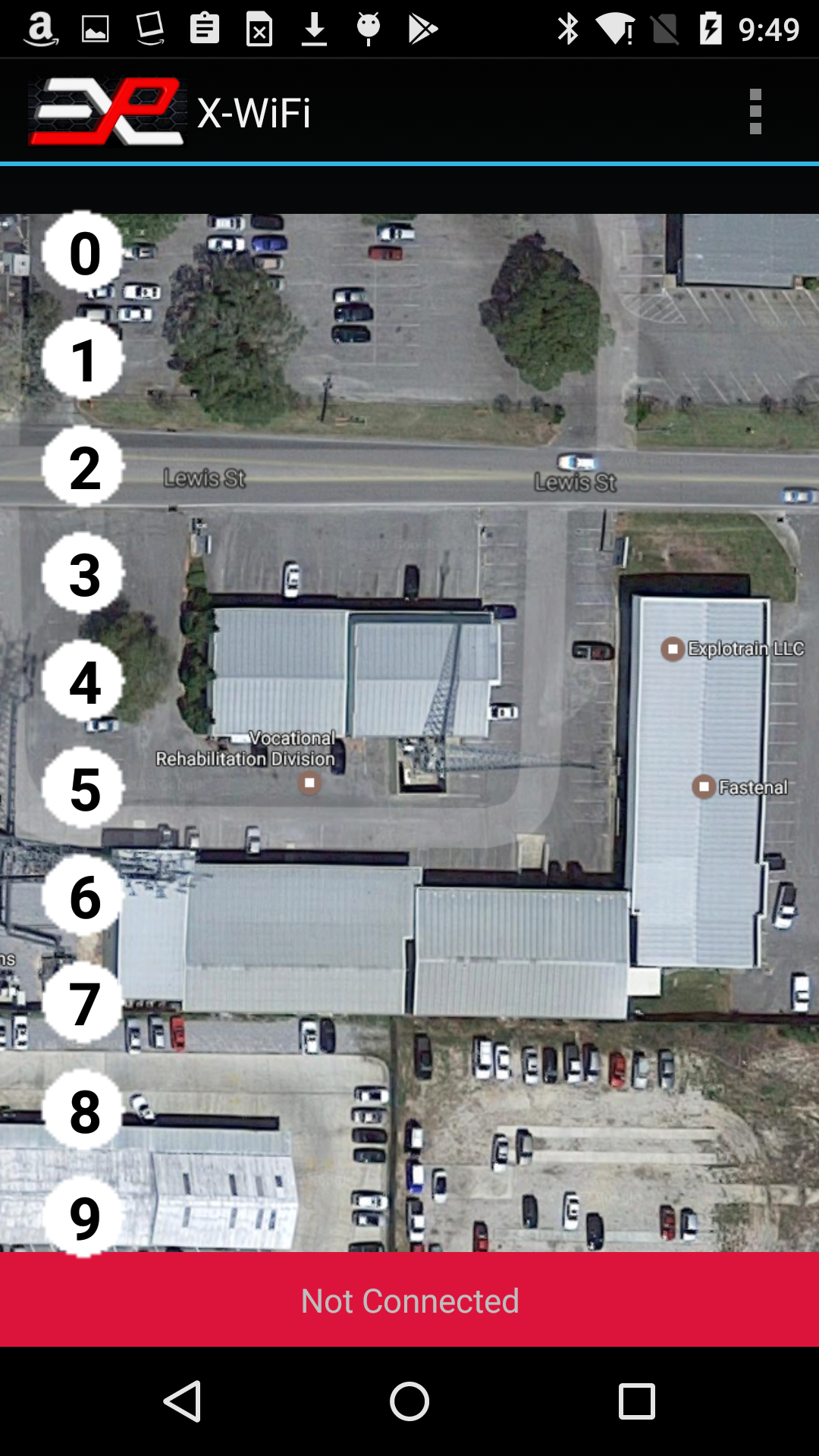
Figure 5: Map View, sample map
The sample map is intended to be used in the portrait orientation.For best appearance, the map should be scaled for the device you are using. To find out the optimum size, click on Help with Maps in the menu after having selected Map View. The Help box indicates the optimum resolution for your device.
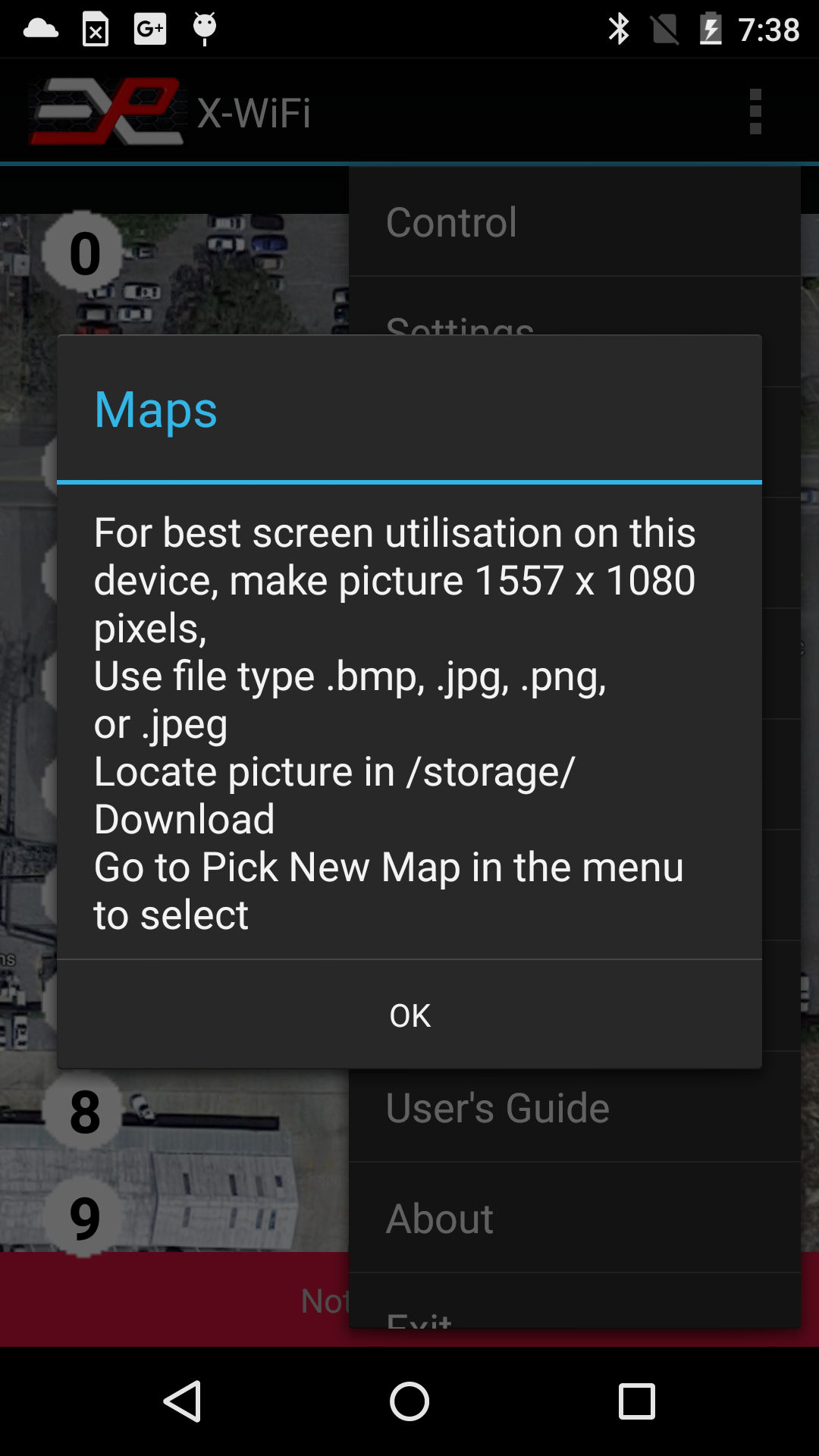
Figure 6: Map View, Help with Maps
Note that the map size and dimensions should account for the orientation of the device. You will normally have two different maps if you want to use the device in portrait and landscape mode.Also it is OK to use a map with smaller, scaled dimensions. For instance, if the app reports the optimum dimensions to be 1557x1080, it is OK to use a map that is 778x540 or close to these dimensions. The first dimension is the vertical dimension followed by the horizontal dimension.
The number of simulators that can be displayed on the map (10 or 16) depends on the "10/16 Units" setting accessible from the Control screen.
Organizing the icons
Once you have loaded a map, the icons will be initially lined up to the side or the top of the display, depending on the tablet's orientation. If you cannot see all the icons, click on Reset Icons in the menu. Note that if the app is currently connected to the X-ACT Bridge Controller, only the icons for the connected simulators will be visible. To see all the icons, go back to Control and disconnect before returning to Map View.You can move any icon into a specific location on the map by selecting "Move Icons" in the menu. Once Move Icons has been selected, the top of the display has a banner indicating you are in the Move Icon mode.

Figure 7: Map View, moving the icons
Simply touch the icon for the simulator you want to move. The number corresponds to the simulator's address. Then touch the display in the location where you want to move the icon to.Once you have moved the icons in the desired position, select "Save Icons Positions" in the menu. The icon positions are not associated with a particular map, so if you change the map, the icons will not automatically reposition themselves.
Note that the Map View is setup for a particular orientation, portrait or landscape.
Operating the X-ACT Bridge Controller through the app's Map View mode
The graphic in the simulator's icon indicates the simulator's state as follows:- White circle: IDLE
- Green circle: ARMING or ARMED
- Red circle: FAULT
- Red flame: FIRING or FIRE DELAY.
- Short press: alternates between IDLE and ARMED
- Long Press: Fires if the simulator was ARMED, or do nothing if the simulator is in IDLE state.
View Currents
The View Currents feature allows to display currents through the valves and the spark module and is used to troubleshoot overcurrent faults and erratic firing problems.Each time a simulator is fired (X-O, X-CAL), the controller records the current at 1mS interval. Currents in the valves, the spark module and the accessory output (smoke machine) are recorded separately and can be viewed in the app.
To view the valve current for instance, go to the View Current page in the app after firing a simulator.
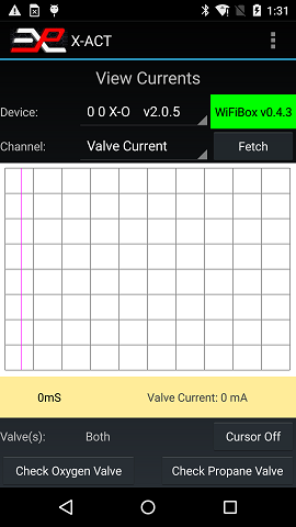
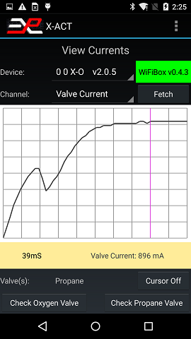
Make sure the right simulator is selected (if there is more than one; in this case there is one X-O at address 0 and it is selected), select Valve Current and click Fetch. The app will download and display the valve current waveform:
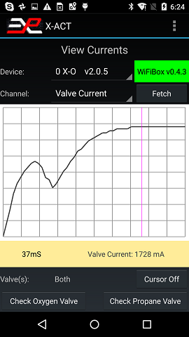
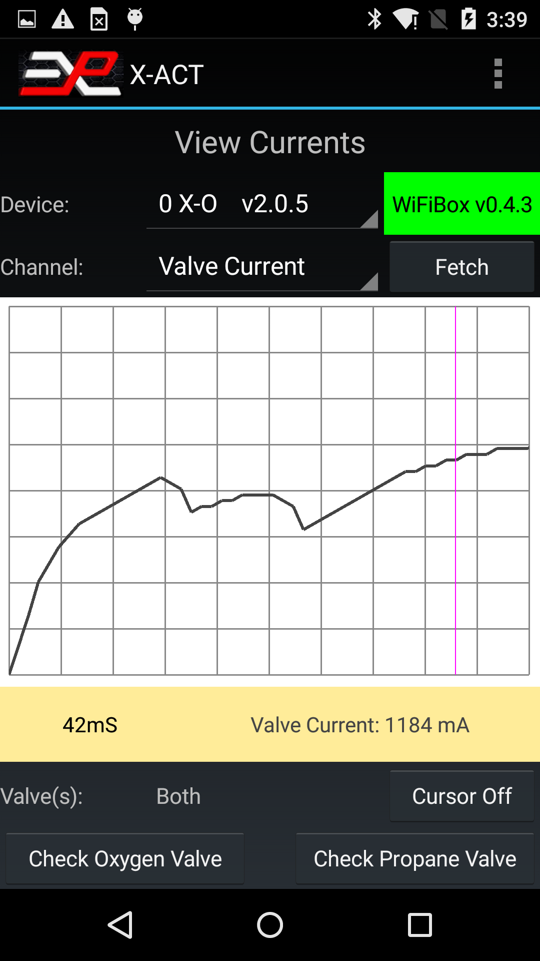
The valve current waveform shows a characteristic hump on the left. This is due to the plungers moving in the valves. That takes typically about 5-12mS, depending on the type of valve and the battery voltage. Once the plungers have finished moving (at the low point in the current waveform), the current increases again until it reaches a steady state value, which is the nominal valve current if you measured it with a hand held meter.
The cursor (the purple line about 2/3 of the waveform to the right) is automatically placed at the highest point on the waveform. In this picture, the valve current is about 1760 mA 37 mS after the valve was powered. You can move the cursor to measure the current at different points in the waveform.
These particular walves are rated 8W each and both together are drawing 1760mA @ 12V, or 21W, a little above the manufacturer's specification of 16W. This is not unusual and is perfectly normal.
Sometimes a valve can get stuck, due to a defect or inpurities in the gas or inpurities being introduced in the hoses during installation. Of course, the simulator will not operate normally with a stuck valve. If a stuck valve is suspected, the View Currents feature can be used to identify the problem.
This is what the waveform looks like with a stuck valve:
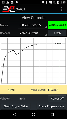
You will notice that the hump is much less pronounced but the total current (as indicated by the cursor) is normal, which is typical of one valve being stuck and the other one working normally. To easily determine which valve is stuck, use the two buttons at the bottom of the screen. First, close both gas regulators to minimize the amount of gas that will be dispensed (this is not necessary but recommended). Then press the Check Oxygen Valve button. The simulator will go through a very short (100mS) oxygen-only valve cycle and immediately display the valve current:

You can see that the Oxygen valve current does not look anything like the waveform in the first picture but the peak current is 928mA, indicating that the Oxygen valve is stuck and not open circuit or in short circuit.
Please note that the app automatically rescales the current waveform to near full screen, therefore even though the peak current is half what it was in the previous picture, the waveform appears to have the same amplitude. To verify the magnitude of the current, use the cursor readings.
To confirm that the oxygen valve is stuck, press the Check Propane Valve button:
This waveform is perfectly normal, confirming that the oxygen valve is the culprit.
Note that if a valve was open or disconnected, the waveform during a normal fire sequence would look like in the last picture (normal waveform, half amplitude).
This feature can also be used to detect worn out rechargeable batteries. Old rechargeable batteries not only do not hold charge very well but their internal resistance increases. This can create a situation where the battery voltage seems correct during normal operation right after being charged, but the voltage will drop rapidly under load such as when the valves are fired. It can be frustrating anf difficult to troubleshoot but the View Current feature will help.
Here is a picture of the valve current with an old battery:
Notice that the total current is low and the hump is distorted compared to the "normal" picture. In this case, it is necessary to replace the batteries. Note that different types of valves may respond differently to low or worn out batteries, but a low total current will always indicate batteries that need to be replaced.
Scripts
Scripts are a powerful new feature allowing you to define a sequence of commands (including precise delays) to be executed automatically.For instance, let's assume that you have 4 simulators connected through an X-ACT Bridge Controller, at addresses 0, 1, 3 and 5. A script may allow you to fire the simulators in any order, with any delay between them in a predictable and reproducible way.
A script is a text file stored in the Download folder of your tablet that contains a sequence of commands and optional delays. Here is an example which arms two simulators, fires them at 1 seconds interval and return them to Idle mode.
	0
	#1,0
	#1,3
	#2,3
	#1,4
	w 800
	#2,4
	w 4000
	#1,2
	w 1000
	#2,2
Here is what this script does:
- "0" this is an ID Query command sent to the X-ACT Bridge Controller
- "#1,0" this command instructs the X-ACT Bridge Controller to send command "0" (an ID Query) to the simulator at address 1.
- "#1,3" this command instructs the X-ACT Bridge Controller to send command "3" (an ARM command) to the simulator at address 1.
- "#2,3" this command instructs the X-ACT Bridge Controller to send command "3" (an ARM command) to the simulator at address 2.
- "#1,4" this command instructs the X-ACT Bridge Controller to send command "4" (a FIRE command) to the simulator at address 1.
- "w 800" this command creates an additional delay between commands of 0.8 second.
- "#2,4" this command instructs the X-ACT Bridge Controller to send command "4" (a FIRE command) to the simulator at address 2.
- "w 4000" this command creates an additional delay of 4 seconds.
- '#1,2" this command instructs the X-ACT Bridge Controller to send command "2" (an IDLE command) to the simulator at address 1
- "w 1000" this command creates an additional delay of 1 second.
- '#2,2" this command instructs the X-ACT Bridge Controller to send command "2" (an IDLE command) to the simulator at address 2
Note that the delay programmed with command "w xxx" is an additional delay between commands and does not include the built-in delay between commands (about 200mS). The built-in delay is the time it takes for a command to travel to the simulator and the simulator's response to travel back to the app. In effect, the delay is measured between the response to a command and sending the next command.
The execution of a script is verified on the screen. The picture below shows the execution of the script above:
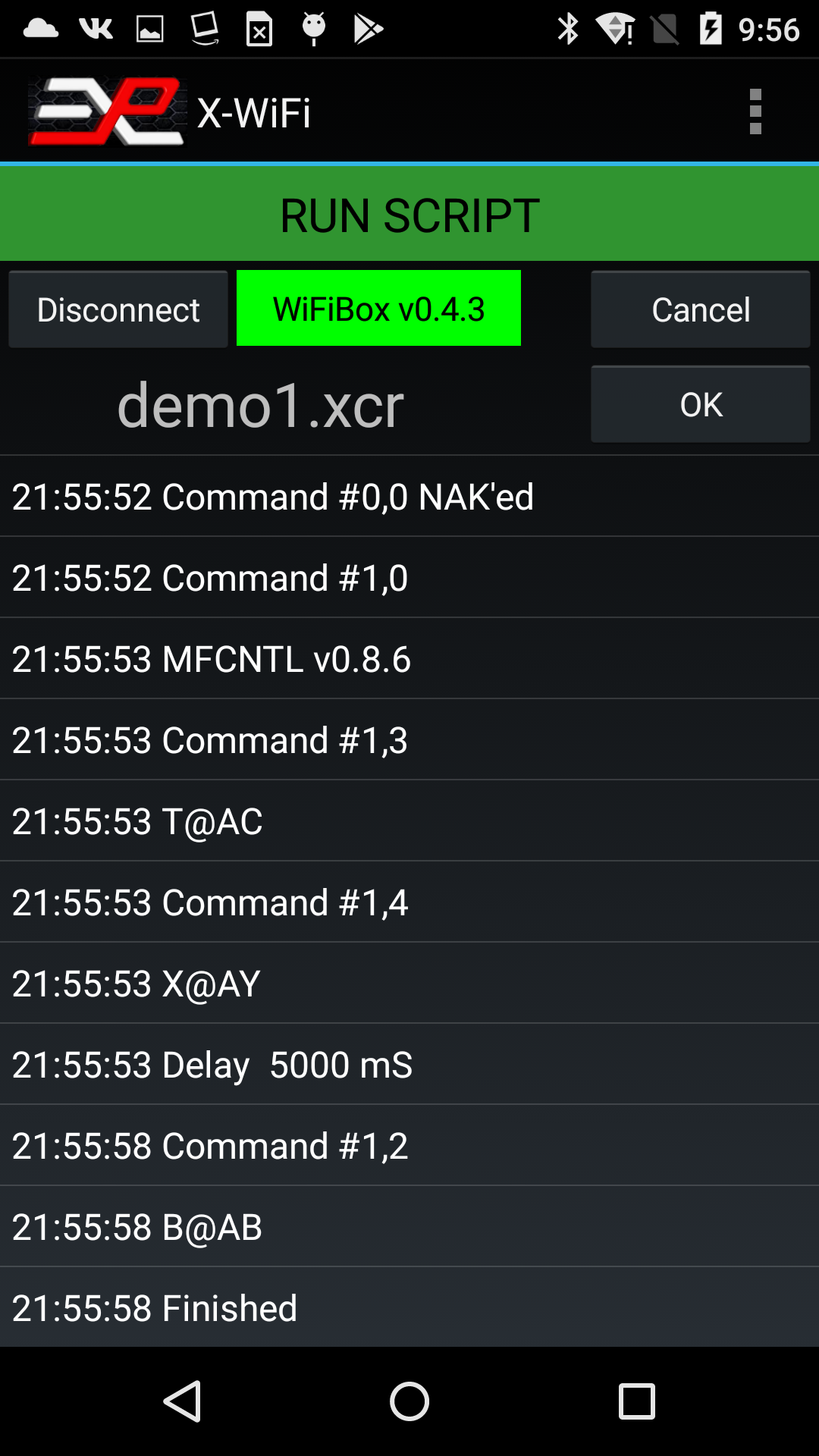
Figure 8: Example of script result
In the screen shot above, the app displays the response to commands ARM, FIRE and IDLE as a 4 character string. This indicates successful execution of the command. A command that cannot be executed would ellicit a response of "NAK", for Not Acknowledge.
Editing a script
To edit a script, simply select a record by clicking on it. Now each record is preceeded with the line number and the currently selected record will be printed near the bottom of the screen for reference and a row of buttons are now displayed right below that at the bottom of the screen as shown below.
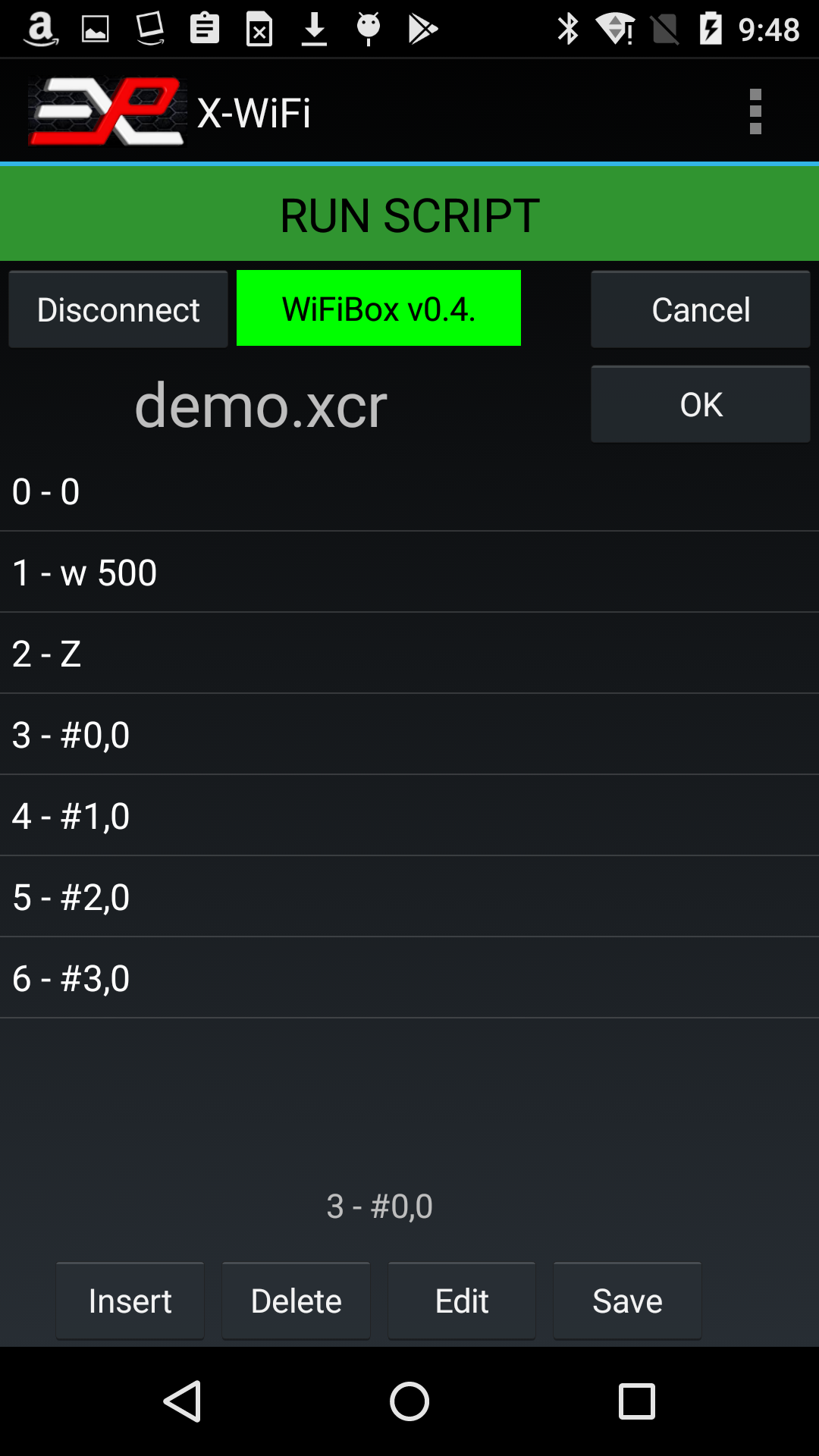
Figure 9: Example of script editing
You can use these buttons to respectively insert a new record (the new record will be inserted in the cursor location, the rest of the script will be pushed down), delete a record, edit a record or save the new script, under the same name or under a new name.
You cannot create a new script from scratch or delete an existing script directly within the app but if you want to create a new script, it is easy to open the demo script, modify it and save it under a new name.
The scripts are saved in the Download folder which makes it easy to exchange scripts via email. Scripts sent via email attachment can be easily saved to the download folder and opened from within the X-ACT app.
Available commands:
The following is a list of the commands most commonly used with scripts:
| Action | Example | Comments |
| Idle Command | '#1,2' | Places the simulator at address 1 in Idle state |
| Arm Command | '#1,3' | Places the simulator at address 1 in Armed state |
| Fire Command | '#1,4' | Executes the firing sequence on simulator at address 1 |
| Wait <xxx> mS | 'w <xxx>' | Maximum: 30000 milliseconds (30 seconds) |
The single quote characters ' are used to show the start and end of the command message. They should not be used in the script.
The "Help with Scripts" menu is useful to remind you of the available commands:
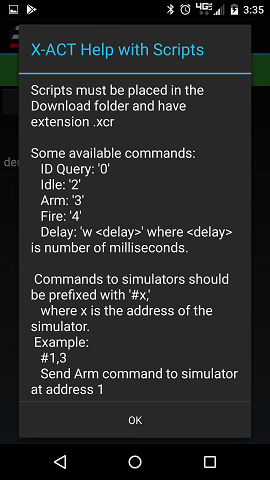
Settings
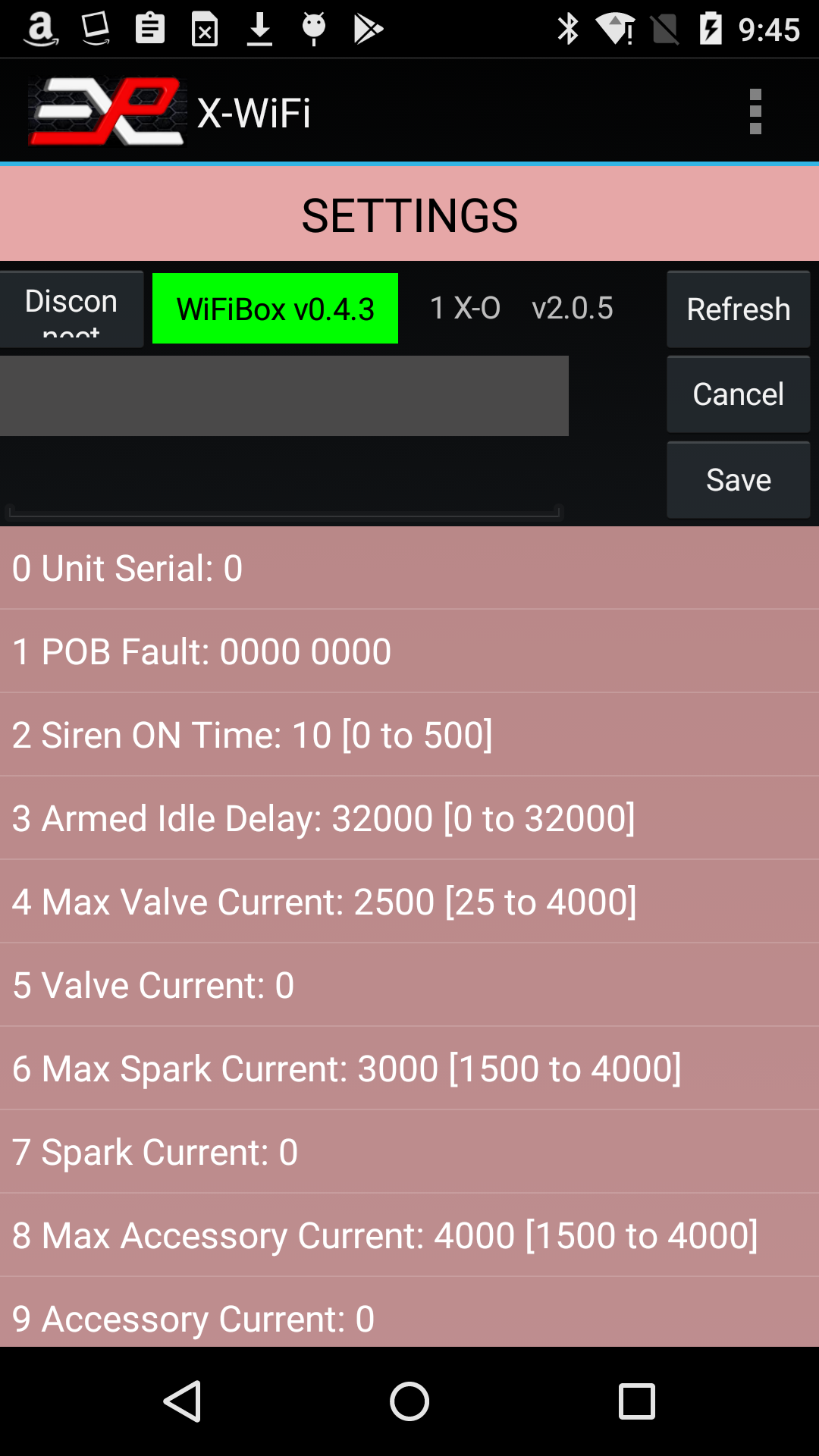
Figure 10: X-ACT Settings page
If the X-ACT Bridge Controller is not connected or has disconnected, click on the Connect button. Otherwise, if the Unit ID label is green, click on the Refresh button. The app may ask you if you want to display the X-ACT Controller's settings or those of one of the simulators. Click on the desired unit. The app will query the available settings for the selected device and display them in a list on the screen.
To change a parameter, scroll the list up and down until you see the parameter you want to change, click on the parameter. This will copy the parameter‘s description and current value in the boxes just above the list (see Figure 9), and a new drop down list is displayed, showing the available settings.
Note that some parameters are Read-Only and cannot be changed. If you click on one of those, the app will flash a brief error message near the bottom of the screen indicating that this parameter cannot be changed.
Select the new setting and click the Save button. A message at the bottom of the screen will indicate if the operation was successful. You can always click Refresh to verify that the parameter was changed as anticipated.
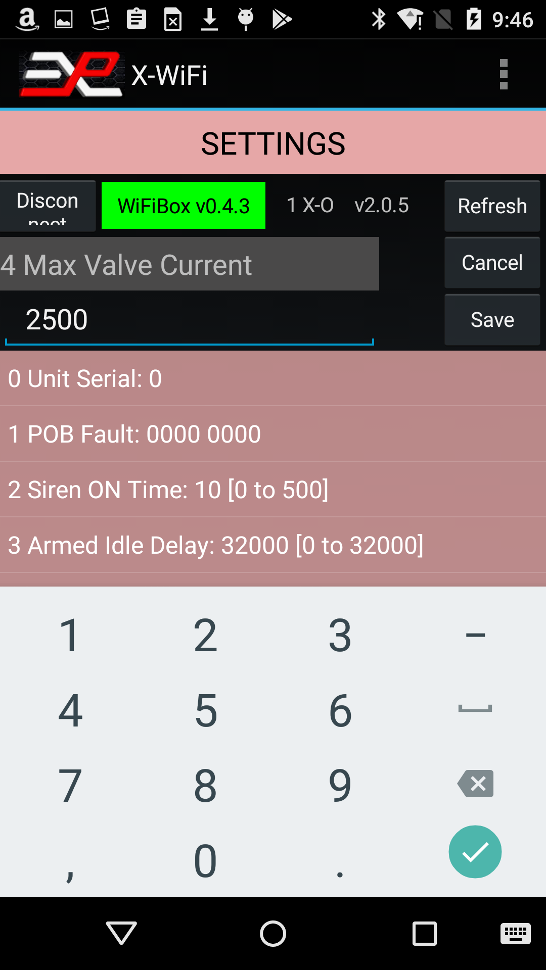
Figure 11: Example of editing a setting
Note that simulators with firmware version below 2.0.0 can be controlled throught the Control screen and Map View but do not provide access to the Settings screen.
Fault Troubleshooting
In section 2, we saw that simulators with firmware version 2.0.0 or later can display faults. In the example, the simulator was showing a "Valve(s) Overcurrent" fault. You can troubleshoot this fault further through the settings menu. By looking up the settings immediately after a Valve Overcurrent or Battery Undervoltage fault occurred, you can help determine the source of the problem.
Here is the Settings for the faulted simulator:
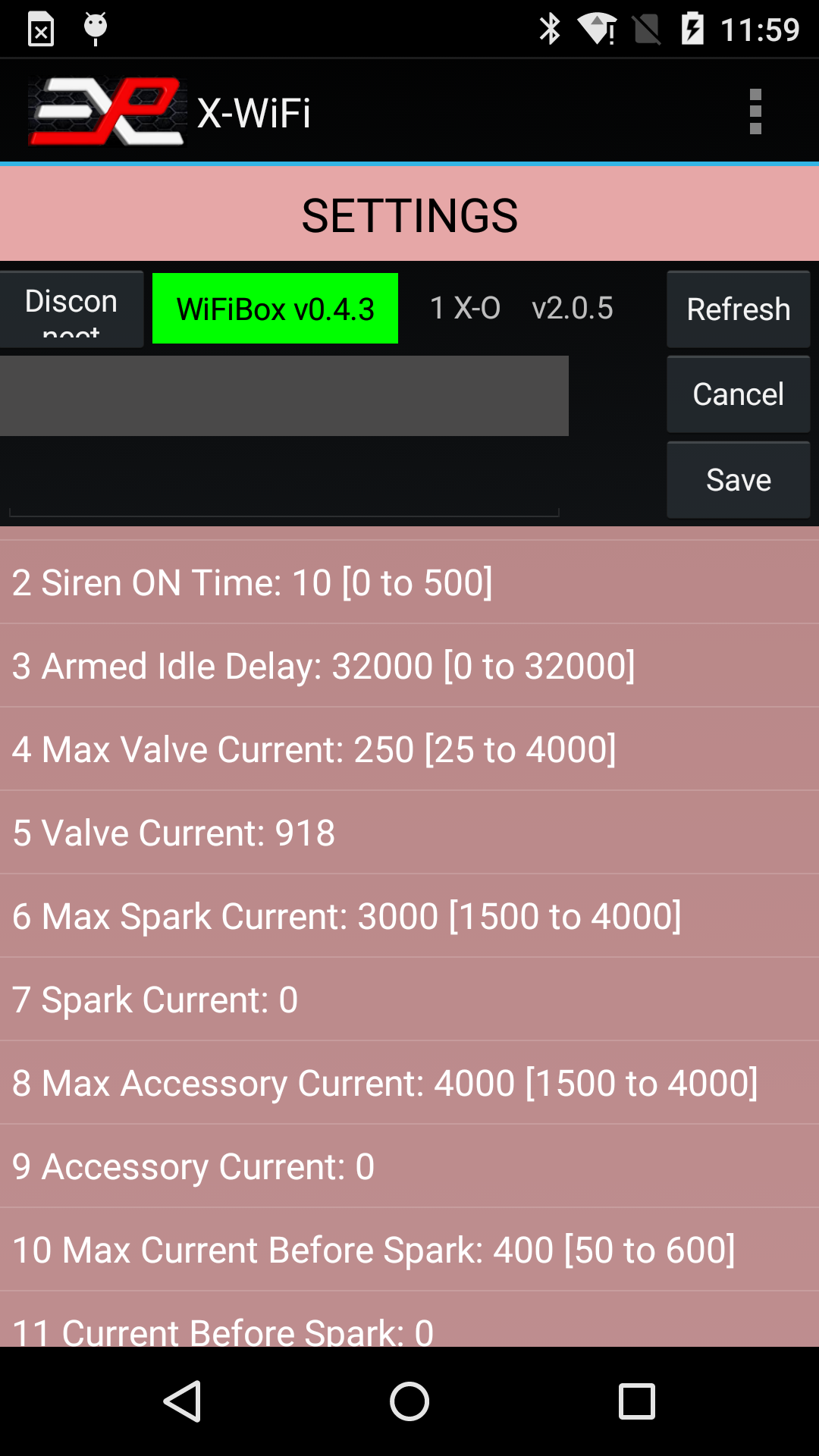
Figure 12: Checking Faults through the Setting screen
On that screen, you can see that the valve current (recorded during the last Fire command) was 918mA (line 5) while the Max Valve Current was set to 250mA (line 4). In this case, the Max Valve Current was set to an artificially low value to force a fault. The normal Max Valve Current setting is 3000mA for most simulators but may vary depending on the application. Always refer to your owner's manual for specific settings for your simulator.Debug
The Debug feature is reserved for troubleshooting under guidance from Explotrain personnel.
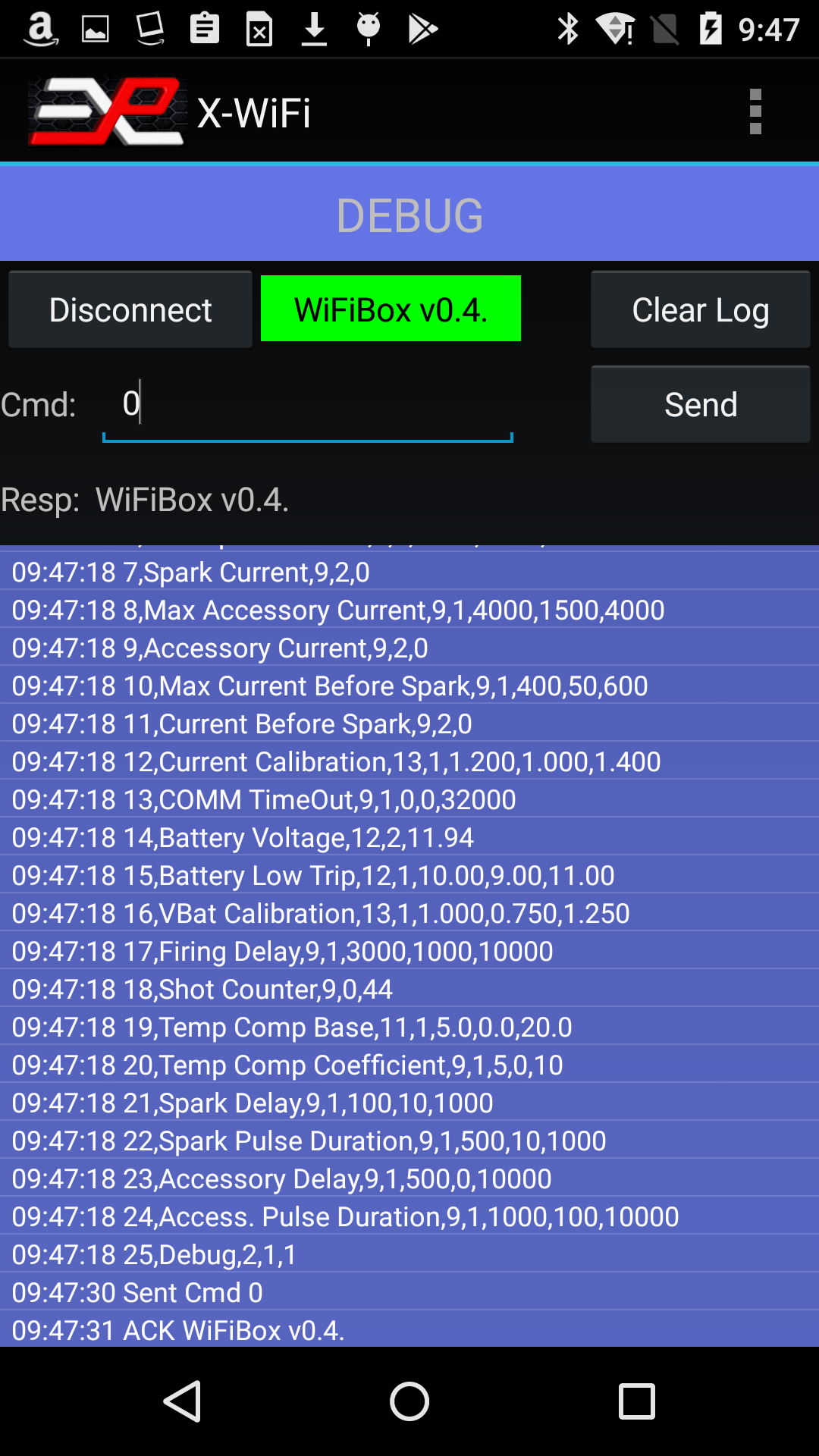
Figure 12: Debug page
The event log records all commands and actions with a time stamp and can be saved to a file on the tablet and emailed later.