X-ACT Manual Settings
Settings
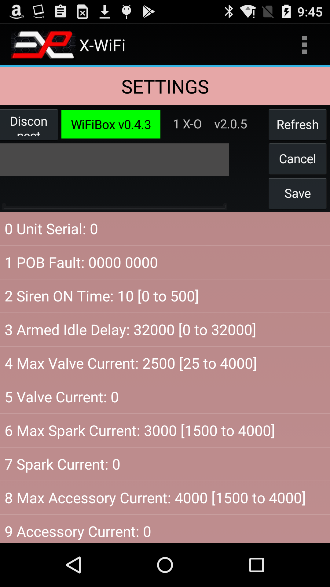
Figure 10: X-ACT Settings page
If the X-ACT Bridge Controller is not connected or has disconnected, click on the Connect button. Otherwise, if the Unit ID label is green, click on the Refresh button. The app may ask you if you want to display the X-ACT Controller's settings or those of one of the simulators. Click on the desired unit. The app will query the available settings for the selected device and display them in a list on the screen.
To change a parameter, scroll the list up and down until you see the parameter you want to change, click on the parameter. This will copy the parameter‘s description and current value in the boxes just above the list (see Figure 9), and a new drop down list is displayed, showing the available settings.
Note that some parameters are Read-Only and cannot be changed. If you click on one of those, the app will flash a brief error message near the bottom of the screen indicating that this parameter cannot be changed.
Select the new setting and click the Save button. A message at the bottom of the screen will indicate if the operation was successful. You can always click Refresh to verify that the parameter was changed as anticipated.
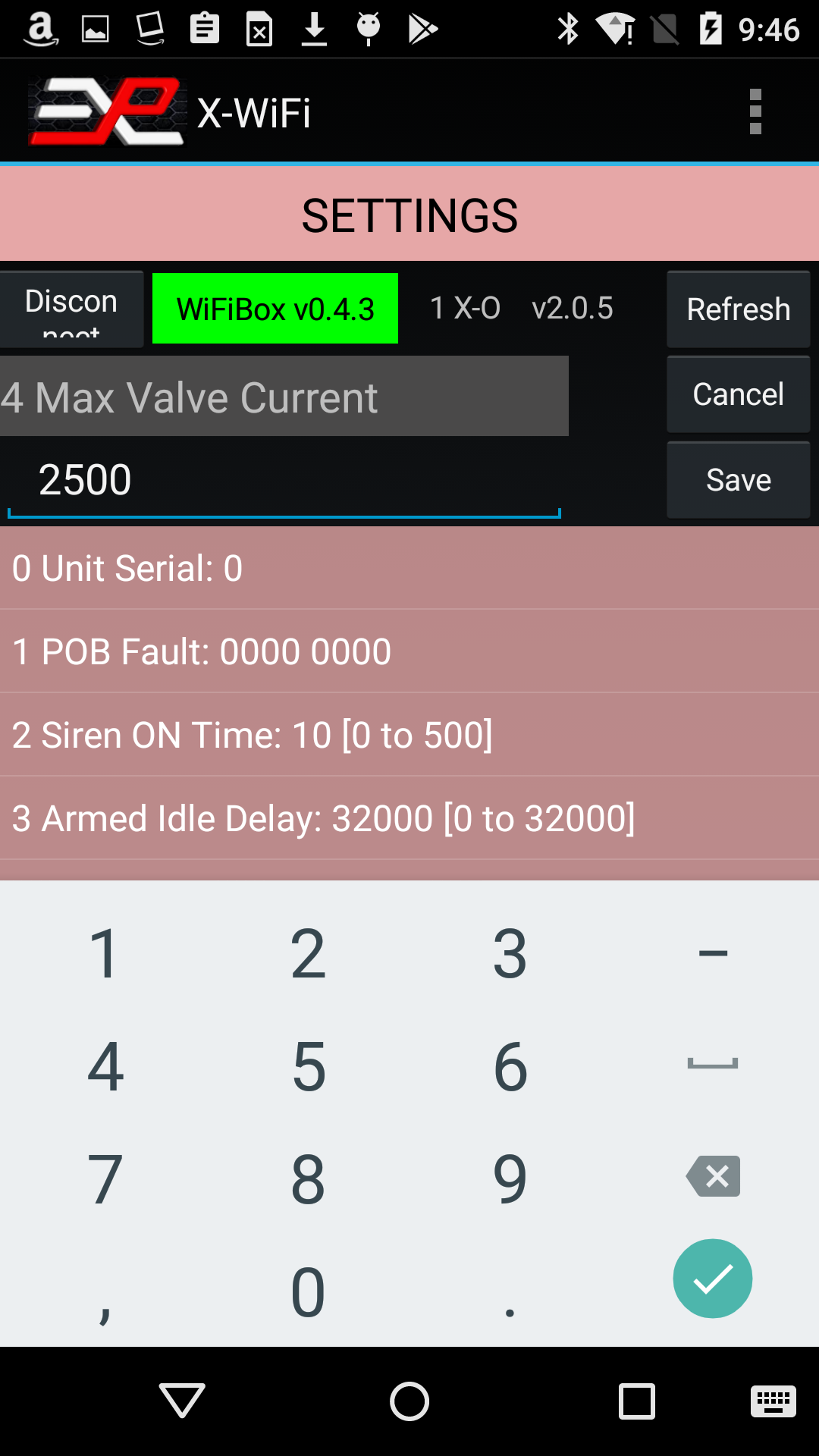
Figure 11: Example of editing a setting
Note that simulators with firmware version below 2.0.0 can be controlled throught the Control screen and Map View but do not provide access to the Settings screen.
Fault Troubleshooting
In section 2, we saw that simulators with firmware version 2.0.0 or later can display faults. In the example, the simulator was showing a "Valve(s) Overcurrent" fault. You can troubleshoot this fault further through the settings menu. By looking up the settings immediately after a Valve Overcurrent or Battery Undervoltage fault occurred, you can help determine the source of the problem.
Here is the Settings for the faulted simulator:
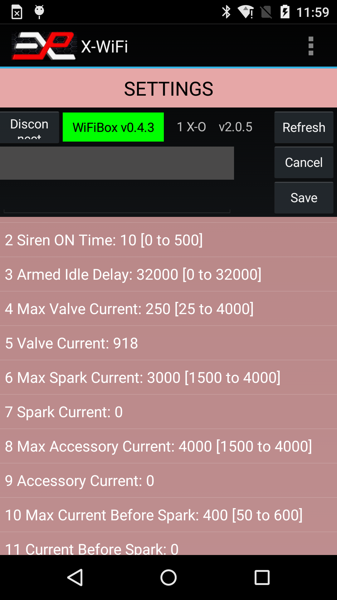
Figure 12: Checking Faults through the Setting screen
On that screen, you can see that the valve current (recorded during the last Fire command) was 918mA (line 5) while the Max Valve Current was set to 250mA (line 4). In this case, the Max Valve Current was set to an artificially low value to force a fault. The normal Max Valve Current setting is 3000mA for most simulators but may vary depending on the application. Always refer to your owner's manual for specific settings for your simulator.