Light Controller Project
The Light Controller is intended to replace older GE Low Voltage Lighting systems.
Low voltage lighting systems use latching relays to control lights. The relays are controlled with 24V through low voltage wiring. My house was wired with telephone 4 conductors cables.
The technology was developed by GE in the 1970's and did not catch up but at the time it was advertised as a modern system and a number of houses were built with it. Mine is one of them.
The system was generally reliable, considering its age but anything eventually fails. The relays and the power supply have been replaced a few times and the relays are becoming very expensive.
Here is a link to a company that is still selling replacement parts and a block diagram of the original system (one light and switch shown):
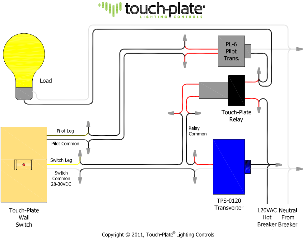
The system includes a relay box (Touch-Plate Relay in the diagram above) with 24V power supply (TPS-0120 in the diagram) in the attic which directly controls the lights, a number of telephone wires one each going to each wall switch (each controlling one light) and a large multi-conductor cable going to the main control panel in the master bedroom which controls all the lights in one location. Pilot transformers (one per light) are used to drive the pilot light indicators in the master control panel.
Note that what is referred to as the Touch-Plate Wall Switch is actually a momentary push-button. Multiple push buttons could be wired in parallel to control a light from multiple locations.
Repairing a 50 year old system with 50 year old parts never appealed to me. On the other hand, it is quite a project to replace these systems with conventional AC wiring as the old low voltage wiring has to be replaced with Romex, which in most cases will require tearing down the drywall at some point. My house being 2 stories, and the system controlling inside and outside lights, the cost of such an overhaul would have been extremely high.
It is also impractical to use modern WiFi controlled switches are these are intended to replace AC wired switches and need 115VAC power to operate. The GE system only provides 24VAC and the low voltage wiring precludes to use of these cables to run 115VAC. This was also not an option here without massive remodeling.
I thought it would be easy to replace the relay box with a microcontrolled system, which could use the existing telephone wires and would offer more flexibility.
So the Lighting Controller was born.
One of the feature of the existing system that I liked was that in addition to individual switches controlling each light, there was a central control panel that allowed to control all the lights in one location, with a small light bulb in each push button to indicate which lights were on. However the stand alone wall switches located elsewhere in the house did not have a status indicator. This was a bit of an issue since the system controlled, among others, the outside lights and during the day there was no way to tell if the lights were on or off unless you went to the bedroom, not the most convenient or logical. On the other hand, being able to tell if the lights were on before going to bed, or being able to turn all the lights on from the bedroom were useful features.
I wanted my replacement system to indicate the state of each circuit on the switch itself and also be able to control the lights from multiple places, using the existing wiring.
It turns out that while the light switches only required two wires, the house had been wired with 4 conductors telephone wire for each switch. This is exactly what's needed for an RS-485 network with 2 wirres carrying 5 or 12V housekeeping power and 2 wires for bi-directional high noise immunity communication. Now I could have some smarts in the wall switches themselves.
Here is the block diagram of the new system:
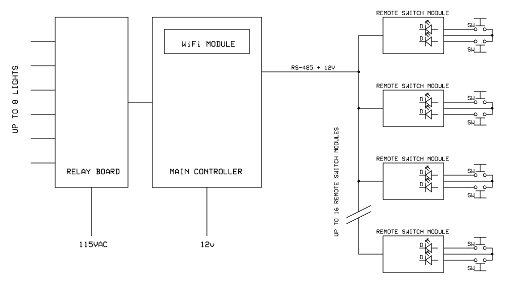
System Block Diagram
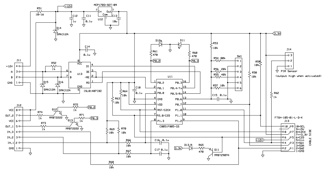
The main controller is capable of controlling up to 8 outputs and is equipped with a WiFi module and a transient protected RS-485 driver. It replaces the old Touch-Plate Relay box.
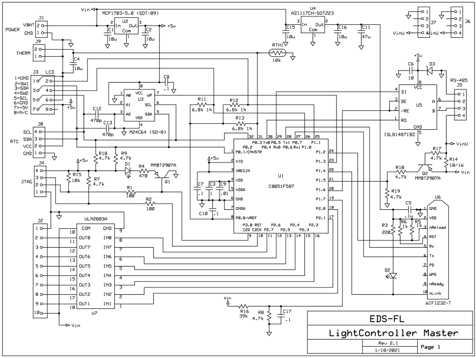
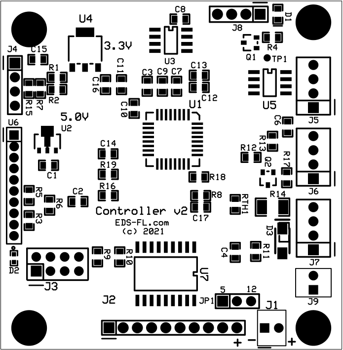
Main Controller Schematic
The Main Controller drives an 8 channel relay module of a type widely available on Internet sites like eBay and AliExpress.
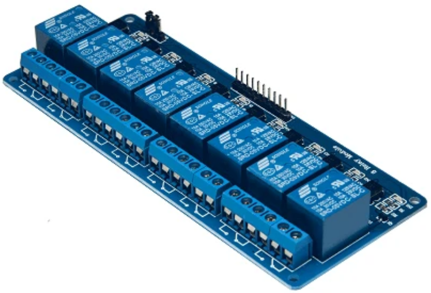
8 Channel Relay Module
A side advantage of the RS-485 network and microprocessor control as opposed to the old system's hard wired switches and latching relays is the ability to reconfigure the switches and change which light they control without having to mess with the wiring itself. So my system takes advantage of that. An Android app communicating with the main controller via WiFi is used to do the initial switch configuration (which switch controls which light) and save it to non-volatile memory in the controller itself. Once that is done, the app can also be used to control the switches but it is not necessary for normal operation. It is convenient however to be able to tell if any light is on before going to bed, as with the old system, or to quickly turn on the lights from your phone, wherever you are in the house.
Each remote switch module is identified with a Hex rotary switch which defines the address of the switch module on the network. Each remote switch module supports two push buttons and two LEDs, and therefore can control one or two light circuits. The LEDs are used to indicate the state of the selected light circuit. The Hex switch allows up to 16 remote switch modules on the network. Since each module supports 2 switches, there can be as many as 32 individual switches on the network, more than necessary to control 8 outputs.
Remote Switch Module Schematic
The switch module circuit card was designed to be the size of the wall switch, small enough to fit inside the wall box with the switch itself. I was not able to find wall-mounted low voltage switches with a built-in LED but it was not hard to modify off-the-shelf low voltage switches and add an LED.
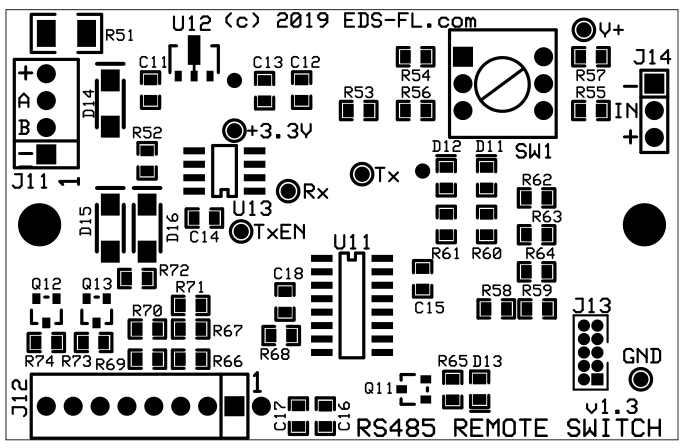
Remote Switch Module
The RS-485 network operates at 9600 Bauds, which provides quick response.
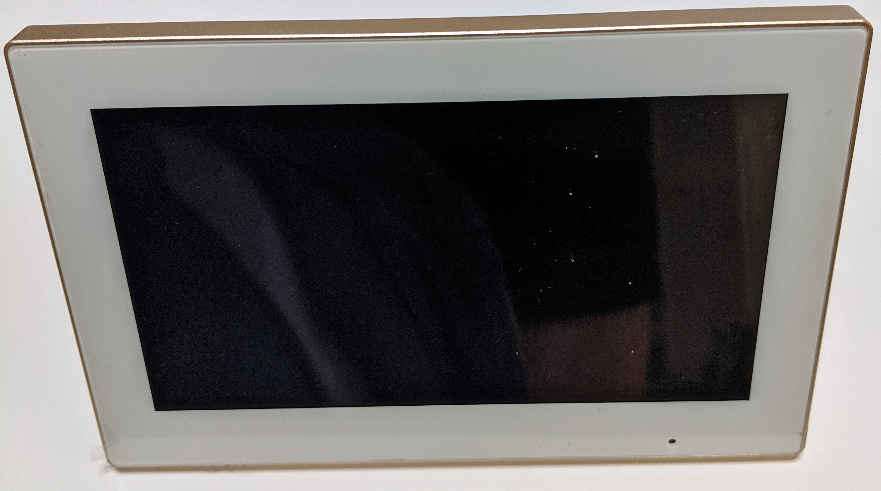
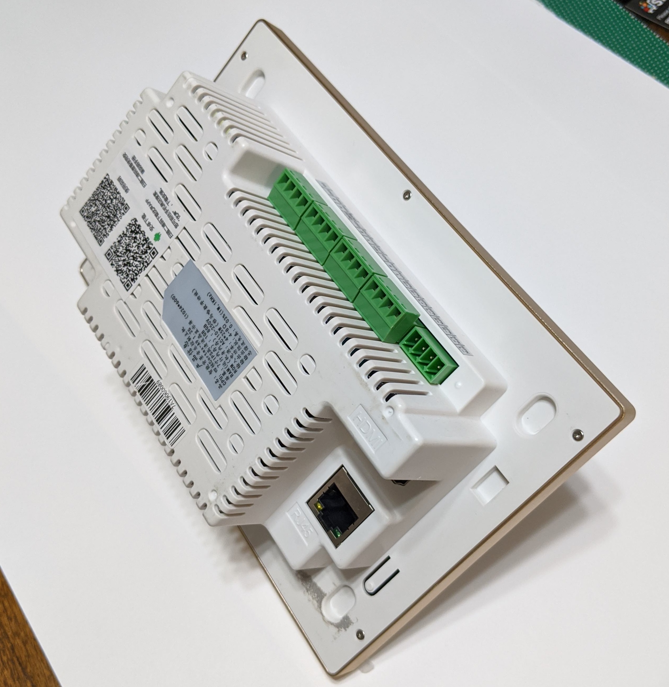
Android Tablet
To emulate the previous central control panel, a wall mounted, AC powered 7" Android tablet (originally designed for home automation and multimedia projects) is installed permanently in a central location running the Light Controller app. Additional phones or tablets can also be used if you wish.
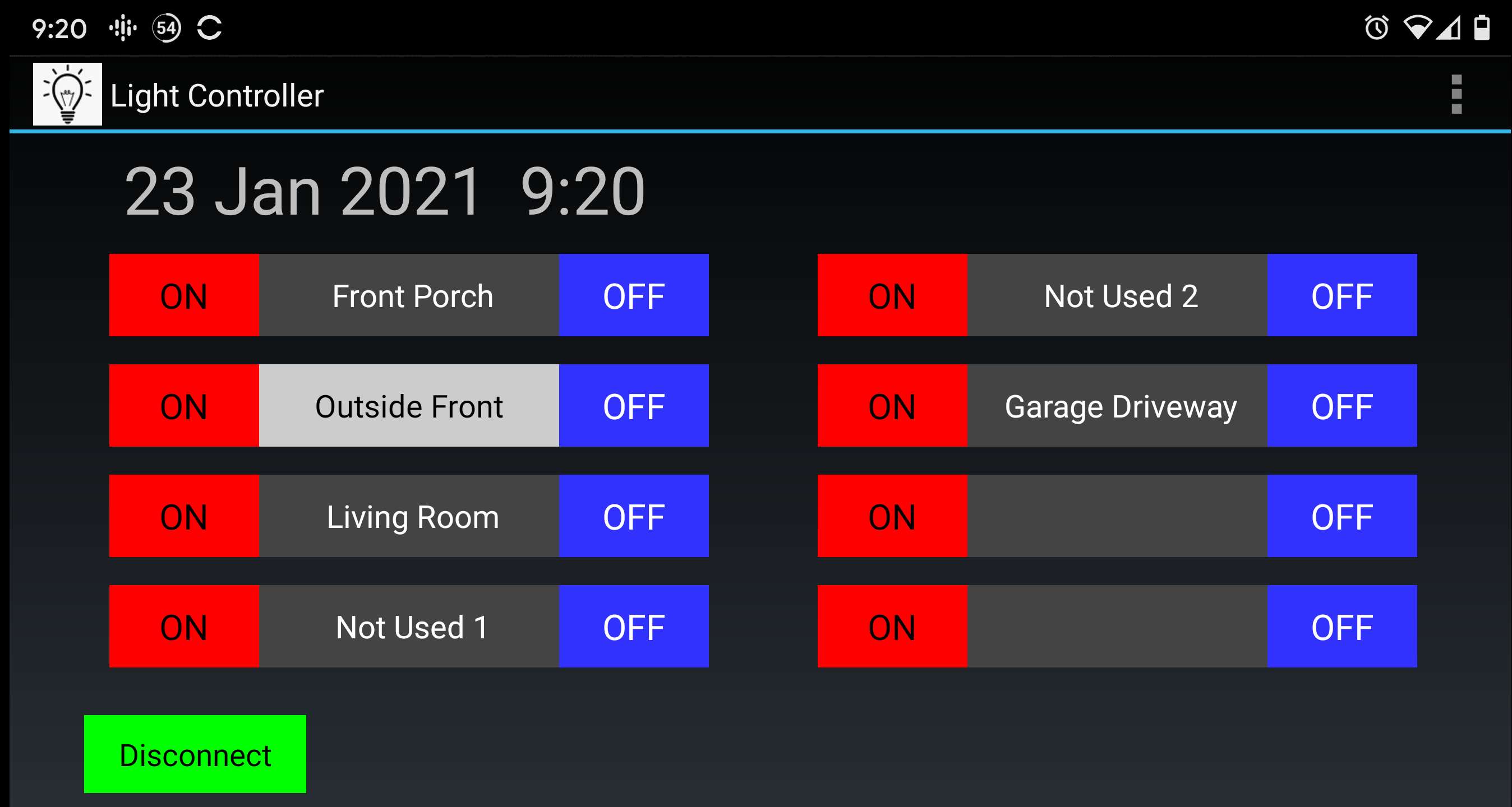
Android app
The companion app runs on any Android device. More details can be found in the app page: Light Controller App.
This is what it looks like on the wall mounted tablet:
Operation
When the wall switch is pressed (it is a push button in this system like in the original GE system), the remote switch processor sends a message to the main controller indicating that the light state should be changed (on if it was off, and off if it was on). The main controller executes the command and sends the new state of the light to the switch module, which uses that information to turn the LED on or off.
Each switch is associated with a specific light but more than one switch can be associated with the same light, emulating the two way and three way switches people are accustomed to without the expanse of wiring and with the capability to easily reassign any switch to any light through the app.
Note that even with multiple switches controlling a single light, the LEDs always reflect the state of the controlled light, independently of which switch has been used. That also applies to the app where the light name is displayed in black font over white background when the light is on, and in reverse colors when it's off.